This entry is a continuation of my series on learning the UML. This entry covers Use Case Diagrams. This entry builds on top of my entry on requirements gathering which was posted last week. I will be using the requirements document created for that entry to build use case diagrams. You may wish to review that entry.
The Use Case Diagram
Use Case diagrams areUML: Use Case Diagrams the first stop when designing an application using UML. Use Case diagrams illustrate your system requirements in terms of system users and the actions they perform. Use Case diagrams build on to your requirements document and are intended to be readable by both technical and non-technical people. In other words, you should be able to show your Use Case diagrams to your client or boss and they should be able to glean a high level understanding of how users interact with the system.
Uses Case diagrams are used to analyze and illustrate the functionality of the system. They show the process flow the steps taken by users to perform a specific function.
Use Case diagrams are also frequently used to illustrate test cases for quality assurance. Because Use Case diagrams are so effective in illustrating process flow they are also very effective in validating that a process flow works correctly.
The Scope of Use Cases
Typically there are several Use Case diagrams for a system. Each Use Case diagram focuses on one functional objective of the system. For smaller systems you may have only a few Use Case diagrams. For a complex system made up of multiple subsystems you may have a much larger number of diagrams.
Use Case diagrams illustrate how the users and a system work together, or interface, to accomplish a specific goal. As a result, a Use Case diagram tends to treat the system like a black box. You shouldn’t care about what’s going on under the hood, only what the user is doing though their interface into the system.
The Anatomy of a Use Case Diagram
Let’s jump in head’s first and take a look at a simple Use Case diagram.

This use case demonstrates the three basic components of a Use Case diagram.
- Actors
- Use Cases
- Relationships
Many UML diagrams also include a construct known as the system. Systems denote the borders of your system. These are not required and I will not be addressing them.
Actors
Actors represent something which interacts with the system. Actors can represent people or other systems.
Actors do not represent individual people. Actors represent a role a person or system fills. For instance, Stock Clerk, Teacher and Cache Manager are all reasonably good Actor names. Imagine how hard it would be to identify each individual who would ever use the system! You can’t, so don’t bother! Just remember to identify actors based on their role.
In Use Case diagrams Actors are depicted as a stick figure. The Actor’s name is shown below the actor. Sometimes actors are depicted using the classifier notation from Class Diagrams.

The illustration above shows the two actors from our example Use Case Diagram. The Search User Actor is shown as the typical stick figure. The Index Searcher Actor is being depicted using the classifier notation. When shown this way the text “<<actor>>” is shown above the Actor’s name. (The “<<” and “>>” marks are called guillemets.)
Use Cases
A Use Case diagram would be pretty useless without having Use Cases. (No pun intended.) A Use Case is an action an Actor takes on the system. Usually, Use Cases are composed of a verb and a noun. The Actor performs the verb on the noun. For instance, your actor might perform the Use Case “Run down street” or “Jump over shark”.
Use Cases can be created with any level of granularity. They can be extremely specific to the point where one Use Case is one step. Use Cases can also be more general and require multiple steps to complete.
A Use Case is displayed as text inside an oval. Sometimes Use Cases are shown as ovals with text below them.

The three Use Cases above are from the example Use Case diagram. As you can see, they all specify an action an Actor can take on the system.
Relationships
Relationships are the simplest element to draw. Despite their simplicity, relationships are what tie the diagram together. Relationships indicate associations between actors and Use Cases.
In the example diagram above we see that a Search User provides search criteria. Additionally, the Search User is involved in the Return Search Results use case. Based on the diagram, we can tell that the Search User does not identify matching content.
The Index Searcher is involved with the provided search criteria. The Index Searcher identifies matching content and returns the search results.
Relationships are simply drawn as lines between Actors and Use Cases.

In this example the relationship is the line drawn between the Driver actor and the Drive Car Use Case. By reading this we know the Driver can drive the car.
Advanced Relationships
Use Case diagrams have another set of relationships which add detail to your diagrams by explaining more specific types of relationships.
- Generalizations
- Includes
- Extends
Generalizations
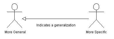
A Generalization is a type of relationship where one Actor or Use Case is a more generalized version of other Actors or Use Cases. If you were to think of a Generalization relationship in terms of classes or ColdFusion components, Generalization would represent an “extends” relationship where a set of classes extend a super class. Each of the extending classes inherits all of the methods and properties of the super class. The super class is a generalization of the extending classes.
The example above shows a Doctor, Lawyer, and Programmer. All of these actors are Professionals. The Professional actor is a generalization of the other three actors. I tend to think of Generalization as an “Is a…” relationship.
The next example shows that generalizations can also be used with Use Cases.

This diagram states that the Index Word Doc, Index HTML and Index PDF Use Cases all extend the Index Text use case. They all perform the same function as Index Text, but with their own specific extensions.
Generalizations are drawn as a solid line with a hollow triangular arrow. The arrow is drawn pointing towards the Generalization.

Includes
An Includes relationship is used to indicate that a particular Use Case must include another use case to perform its function. The following example illustrates an Includes relationship.

This example illustrates a bank’s Account Holder withdrawing cash. The Withdraw Cash Use Case can not be preformed without debiting the Account Holder’s account. Potentially, the Debit Account Use Case could be reused elsewhere.
An Includes relationship is drawn as a dashed line with an open arrow head. The arrowhead points at the Use Case being included. Along the line somewhere is placed the text “<<include>>”, surrounded in guillemets.
Extends
When getting started with Use Cases I had a really hard time understanding the difference between a Generalization relationship and an Extends relationship. This was especially hard for me because the Generalization relationship illustrates what would programmatically be one class extending another. In a Use Case Diagram an Extends relationship is a different concept!
An Extends relationship is exactly like an Includes relationship with one important difference: An Extends relationship is a conditional include. For example consider the following diagram.

This diagram shows that an Employee does work. A Manager, which is a type of employee, also does work. Conditionally, the manager can give the Employee a raise.
One problem with this diagram is that we can’t easily tell why the manager might give the Employee a raise. To clarify this, Use Cases have an additional type of nation known as extension points. Here is the same diagram with an extension point drawn in.

This extension point indicates the circumstances when the Extending Use Case will be performed. In this example the manager will give the employee a raise when they do good work.
An Extends relationship is drawn as a dashed line with an open arrow head. Unlike an Includes relationships which point at the Use Case being included, an Extends relationship points at the Use Case which conditionally includes the other Use Case. Along the line somewhere is placed “<<extend>>”, surrounded in guillemets. In the diagram above, the open arrow head is shown pointing at the Do Work Use Case which conditionally includes the Give Employee Raise Use Case.
Extension points are draw by bisecting the extending Use Case oval with a horizontal line. The Use Case name goes on the top segment of the oval. The Extension points are listed in the bottom half under the phrase “Extension Points” which is shown in bold.
As a note, while researching this entry I saw a number of different styles of notation for Extends relationships. Many of the examples I saw blurred the line between Generalizations and Extends. Both styles are perfectly valid. I am blogging on how I do mine. You’re welcome to apply any style you want, so long as your diagrams communicate your purpose effectively.
Let’s Create Our Use Case Diagrams
One of the purposes of this series on UML is to apply UML in the real world. As a part of this, I am using the lessons learned to design a search engine API for ColdFusion around the Lucene search engine libraries. In a previous blog entry I created a requirements document which I will now use to create a set of Use Case Diagrams. Follow this link to read the requirements document in PDF format.
Note: I am creating all of my UML diagrams using the Community Edition of Gentleware’s Poseidon for UML software.
Skipping to the Business Requirements section of my requirements document, I see that there are two business processes identified, Index Content and Search Content.
The Index Content Use Case Diagram
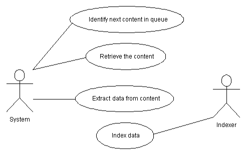
The requirements document describes the business process of indexing content. The description states that the system will use a queue to identify what content to index. The system will then get the content and extract important data from it. The extracted data is then passed to the indexer which indexes it.
For my first attempt I’m going to draw out what this sounds like.

I may have been getting ahead of myself when I wrote the requirements document. It identifies a few other system users, meaning users which are part of the system. These system users are Content Queue, Content Retriever, Content Inspector, and Indexer. I had actors in mind when I identified them, which might be right and might be wrong.
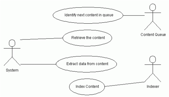
The Content Queue is supposed to be responsible for identifying what content to index. Let’s add this actor to our diagram and see what happens. I think the results should end up looking like this:

The Content Retriever is supposed to be responsible for getting the content to index. As a note, the Search API should be able to get files on the web as well as files on disk.
I just realized that this isn’t covered in my requirements document! I found an omission! I’ll update my requirements document and then update my use case diagram.
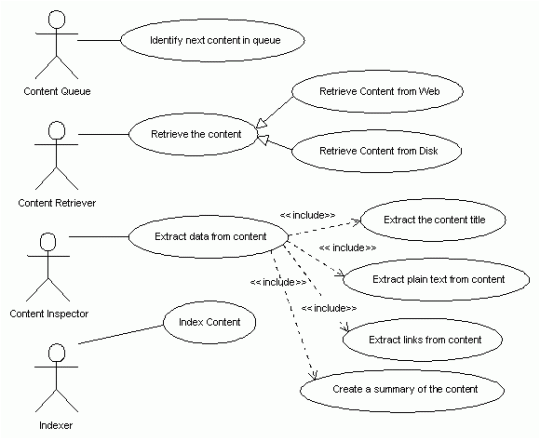
I also see a Content Inspector object which is responsible for interpreting the content and extracting portions of the content to be indexed. For instance, in a HTML document it would extract the plain text of the document and links to other documents.

Because content can be retrieved from the web or from disk I added two use cases which extended the Retrieve the Content use case. Retrieving the content from the web or from disk are both types of content retrieval.
The Content Inspector extracts data from the content. It has to extract the title, plain text, links and summary of the content. Because it can’t perform its function without the support of other Use Cases, I’ve added four includes relationships.
After one more review of the requirements document I found some more information. The next diagram is my first completed version of the Indexing Content Use Case Diagram.

I changed the name of the Content Queue and the Indexer to the Queue Manager and Index Manager, respectively. As I was working on the Use Case diagram I realized that these two actors had more responsibilities than I initially thought. The Queue Manager is responsible for adding addresses into the queue and working with the queue data. The Index Manager doesn’t really do the indexing, Luncene does. The Index Manager is responsible for adding, inserting, updating and deleting content using Lucene.
I also added a number of extension points to the Index Content use case which take care of situations where the Index does not exist, updating content in the index, and adding content into the index. I also added an extension to the Index Manager which deletes content in the case that it’s deemed permanently inaccessible.
I made some changes to how the Queue Manager works too. The Queue Manager is responsible for creating the Queue if it doesn’t exist. This process also needs to identify the first item to index. The requirements document also indicated that the Queue Manager could be told what to get from the queue. Because of this I changed the name of the use case to Identify content. It has an extension which creates the queue when it doesn’t exist. This extension includes the Identify default item use case so that the Queue Manager always has something to work with.
I also added a use case where the Queue Manager adds links extracted from the content to the index. I’m not sure if I’m happy with this, but it will do for now. I can revise this if it’s not correct.
One thing which is not yet addressed in this use case is what happens if the content is temporarily inaccessible. For now, I think this is fine. I should catch this in future updates. Furthermore, the Use Case document should be focused on the main success scenario.
The Search Content Use Case Diagram
The Searching Content Use Case diagram should be a lot simpler than the Index Content Use Case Diagram. The requirements document specifies that the user provides search criteria, the system identifies matches in the index and returns them to the search user. One import note is that this is an API.
The Search User is not really a person, but is a system implementing the API. The implementing system could be ferrying requests to the search system from a web form, Flash, web services, SMS or anything. Given that, I think my two actors will be Search Implementer and Index Manager. The Index Manager is the same actor from the Index Content Use Case.

The resulting Use Case indicates that the Search Implementer provides search criteria to the Index Manager. The Index Manager identifies matching content, presumably by querying Lucene. The resulting matches are return by the Index Manager to the Search Implementer.
There are a few scenarios listed in the requirements document which describe possible negative outcomes. I’m not going to address these now. I’m most interested in the main success scenario. These other outcomes will be addressed in future documents.
Conclusion
Now that we’ve completed this exercise we have a pretty good idea of who the users of the system are and the functionality provided by the system. The Use Cases are clear enough that non technical users can read them with a little coaching.
In all honesty, the Index Content use case might make a few too many assumptions. When writing the requirements document I had some preconceived notions which I was working towards. This might have shaped my approach more than I would like. Time will tell if I got this right.
Our design probably still has some problems. We should expect that. As we move into the next phases of architecture we should be able to uncover some of these. Remember that design is iterative. As you move forward in your design you will learn new things which should then be integrated into previous documents.
One key way in which our Use Case diagram was a success is that the system has remained a black box. We don’t know what the system does behind the scenes. All we know is who the actors are and what they expect from the system. We will figure out how the system will meet these expectations before long.
While working though this process I discovered a number of errors, typos, and omissions in my requirements document. I have now updated the requirements document and created a new version. The new version can be downloaded below. If nothing else, the process of creating the Use Case Diagrams helped us clean up the project requirements.
Comments on: "UML: Use Case Diagrams" (27)
Doug Keen forwarded this URL to me.
http://www.andrew.cmu.edu/course/90-754/umlucdfaq.html
It makes some interesting points which I might have gotten wrong.
Anyone else have any feedback?
LikeLike
Doug K. – I’ve been thinking on your comments. I understand you to say that the Search Index use case diagram should possibly be composed of only one Use Case. On the left would be the Search Implementer on the right would be the Index Manager. They would both be related to one Use Case in the middle, Search Index. This makes a bit of since, though one wonders why the Index Manager is shown at all, as that’s part of the system.
Perhaps you’re correct. Maybe the Search Index use case diagram shows too much sequence. The diagram with one use case would do a beautiful job of explaining functionality of searching the system, at least from the Search Implementer’s perspective.
I think that there needs to be more information from perspective of the Index Manager actor. This actor is who interfaces with Lyris. I think we need to know what functionality this particular user expects. This may necessitate another use case named Search Index. Only the Index Manager would be associated with it. This would do a good job of explaining the functionality of the system from the Index Manager actor’s perspective, would it not?
Now, the one on which I agree the most with you is the Return search results use case. This isn’t really functionality provided the system, so much as a behavior of the Index Manager. Furthermore, from the Search Implementer’s perspective, wouldn’t the returning of results be a part of what happens when the actor searches the system?
Ok. So that takes me back around full circle. Provide search criteria is not the right name for the first use case. It does not imply functionality. It should simply be called "Search system".
Take a look at this diagram and let me know what you think:
The counter argument I can think of on this is that from the Search Implementer’s perspective the Identify matching content use case is a part of the Search content use case. It might be that the Index Manager actor doesn’t belong in the diagram at all.
The only other things I can add of value are that there are a lot of differences in how people write Use Case diagrams. Some use them only as a description of the high level functionality (Create Account, Log In, Change Account, Log Out, Cancel Account, etc). Other people decompose these high level use cases into more detailed use cases, which I think I’ve done.
LikeLike
My my, aren’t we demanding?
LikeLike
The first and may be the only place in the web and Use Case books where I found a clearly explained difference between includes and extends, THANK YOU very much!
LikeLike
The case diagram was really useful. Appreciate more topics on this. Thanks
LikeLike
Good comment
LikeLike
usecase diagram of online exam
LikeLike
usecase diagram on online exam.
LikeLike
Thanks for the info. In a nutshell I understood the concepts.
LikeLike
i am confused between generalization & Extends Relation ship.
I have to show searching on records but on different fields,i can search records on 4 different fields, so how do i show them ?.
by generalization relationship Or by Extends Relationship?
Please help me out.
LikeLike
i want inline examination System
LikeLike
Thank you, I found what i searched for (arrow direction :p). I discover a few things too.
LikeLike
thanks for this type of information
LikeLike
i am doing B.Tech IT 3yrear .i have case tools lab . i want use case diagram,
sequence diagram,collobration diagram
LikeLike
sir need on line exam diagrams
LikeLike
nice explanation..
i want all UML diagrams for managing number of projects in organization.
LikeLike
sir i m confuse between relationship
LikeLike
ur website is fi
ully useless u have to increase the material releated to the any given topic. it should be more clear and to the point. please improve this
LikeLike
Your page did a great job in explaining concepts I had difficulty understanding in class.
LikeLike
i want uml diagrams for the project retrieveing files using content based searching
LikeLike
i want all uml diagrams on search engine
LikeLike
i want the problem statement for search engine
LikeLike
please give reply as early as possible
LikeLike
please give me user diagrams for online examination system
LikeLike
please help me the dead line is very soon please replay as early as possible.thank you
LikeLike
I think people would love to read your article if any broken pic files are fixed.
I welcome for your next article
Rgds,
Satria
LikeLike
please send me uml 9 diagrams for E-compiler for java with security editor
LikeLike