The amazing adventures of Doug Hughes

Archive for March, 2005

UML: Activity Diagrams

In my last major entry on the UML I covered the Use Case diagram. The Use Case diagram is a diagram used to gather requirements and help with analysis. Once you have gathered your Use Case diagrams you can continue on with the analysis phase by using Activity Diagrams.

Activity Diagrams are used to illustrate the activities implicit in a use case. For example, consider this Use Case diagram:

UML Activity Diagrams 1

This Use Case diagram clearly states that Search Users will Search Content. However, it doesn’t make any attempt to say anything about the steps involved. This is where Activity Diagrams come in.

Activity Diagrams are very similar to standard flow charts. The major difference is that activity diagrams allow for parallel processing of tasks. (In the ColdFusion world you really don’t need to worry about this difference.)

Here is an example Activity Diagram illustrating the Get Out of Bed use case:

UML Activity Diagrams 2

This diagram is made up of the following notational elements:

Activities

UML Activity Diagrams 3

Activities are used to indicate actions which are preformed in your diagram. In the previous example the activities were: Alarm Goes Off, Hit Snooze, Shut off Alarm and Get Out of Bed. Activities are shaped like pills and have a description inside.

Transitions

UML Activity Diagrams 4

The lines with open arrow heads are called Transitions. Transitions are used to indicate the process flow between elements in your diagram. In the Get Out of Bed example above, you can see that the Alarm Goes Off activity transitions to the Sleepy state. There are nine transoms total in the example.

Decision Points

UML Activity Diagrams 5

There are two ways to draw logical branching in activity diagrams. The Get Out of Bed example uses a decision point “Still Tired?” If Still Tired? is Yes then the flow transitions to the Hit Snooze activity and then back to the Asleep state. If Still Tired? is No then the flow transitions on to the Shut off Alarm and Get Out of Bed activities.

The text shown in square brackets on transitions out of the decision points is called Guards. For flow to progress through a guarded transition the guard must evaluate to true in the context of the decision point. For example:

UML Activity Diagrams 6

This rather simplified diagram illustrates the decisions involved in buying a car. We can see that if we’ve got less than a $100 we’re going to be stuck in a used Yugo. However, as long as we don’t have too much money we’re going to be able to drive a Sensible Car. And, if we happen to have too much money we’re going to end up with a nice sports car.

Guards need to be mutually exclusive. For instance, it wouldn’t make since in the diagram above to show that if we have more than $100 that we’ll buy a sensible car, because that could overlap with Too Much Money guard and we wouldn’t know what to do.

You don’t need to use decision points to show decisions. You can also simply draw multiple guarded transitions out of an activity. Here’s the car buying diagram again, this time without the transition point:
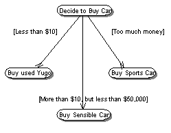
UML Activity Diagrams 7

In general, the decision to use Decision Points is up to you. (Frankly, no one seems to use the same conventions in UML diagrams anyhow, so you could probably use pink elephants to indicate decision points, so long as you’re consistent!)

States

UML Activity Diagrams 8

States are represented by rounded rectangles. (Sometimes they are segmented like in the examples above, sometimes they’re not. As far as I can tell, there’s no difference.) States are used to indicate milestones in processing of your activity diagrams.

In the example above there are three states, Asleep, Sleepy and Awake. These indicate the “state” of the person being woken up.

Starting State

UML Activity Diagrams 9

Start States are a special type of state indicating the starting point for your activity diagram. There can be only one start state on your diagram. Starting States are always drawn as a filled circle. Sometimes people draw a descriptive caption underneath the Starting State. In the Get Out of Bed example we could probably have gotten rid of the Asleep state and called the starting state Asleep instead.

Ending State

UML Activity Diagrams 10

Ending States are similar to Starting States; accept that they indicate ending points for processing. The other big difference is that there can be multiple Ending States on your diagram. Ending States are drawn as a filled circle with a ring around it. (It makes me think of Saturn, for some reason.) As with Starting States, sometimes people draw a descriptive caption underneath the Ending State. In the Get Out of Bed example we could probably have gotten rid of the Awake state at the end and called the Ending State Awake instead.

Forks and Joins

Seeing as my audience is primarily ColdFusion programmers, forks and joins probably won’t make much of a difference to you (unless you use ColdFusion MX 7 Enterprise, which now has an asynchronous event gateway). However, for the sake of completeness I will do a brief overview of them.

Forks and Joins are shown as black bars and are used to indicate parallel processing. For an example, look at this diagram:

UML Activity Diagrams 11

This diagram illustrates the process of getting in the shower. The diagram starts with the Turn on Shower event. However, the shower always comes on cold and takes a while to warm up, so, for the sake of efficiency, we will fork out and do more than one thing at a time. In our example, while we Brush our Teeth and Shave we are also busily waiting for the water to get warm and happily wasting precious natural resources. When we’re done with all of that, we will join our processes back together and Get in Shower and proceed to play with the Rubber Ducky.

Forks are always shown as a solid bar with one entry transition and multiple exit transitions.

Joins are always shown as a solid bar with multiple entry transitions and a single exit transition.

Swim Lanes

There is one other big notational element to activity diagrams, Swim Lanes. Swim Lanes are used to illustrate which portions of a system are responsible for particular elements of your diagram. Here’s an example:

UML Activity Diagrams 12

This diagram illustrates a User and a Website. The user is attempting to log on to the website. As you can see, the User is responsible for providing login credentials, while the Website is responsible for authenticating the user.

One thing about swim lanes which confuses me is where elements like Show Error Message or Show Intranet should be placed. I put them in the User column because the User sees it. However, it’s really the website which performs the action of showing, isn’t it? My opinion is that it doesn’t really matter where these are placed. The purpose is to show that the User and the Website work together to Authenticate the User and Show the Intranet.

Note: The diagram above is interesting too because it shows multiple Ending States, one for success and one for failure.

How to Draw Activity Diagrams

The process for creating activity diagrams is pretty simple. You can accomplish it by following these steps:

  1. Identify a Use Case you want to create an Activity Diagram for.
  2. Draw a simple Activity Diagram which shows the primary success scenario from beginning to end. Don’t worry too much about details yet.
  3. Go back and add in alternative paths through the use case, including those which will result in errors.
  4. Add detail to the diagram.

As a note, you might end up with portions of your diagram which are so complex that they warrant an activity diagram. This is part of the point of these diagrams. This level of discovery helps you understand the scope of your software.

Let’s Draw Some Diagrams

In previous entries on UML, I created a requirements document and Use Case diagrams for a searching and indexing API for ColdFusion based on Lucene. I will now use the Use Case Diagrams to create a set of Activity Diagrams.

Search Content

The Search Content Use Case diagram was pretty simple:

UML Activity Diagrams 1

I started diagramming by creating a simple Activity diagram which illustrated the primary success scenario.

UML Activity Diagrams 13

Now that I have the primary success scenario I need to go back and add some detail. For instance, what happens if I don’t provide any criteria or what happens if the index I’m searching doesn’t exist?

UML Activity Diagrams 14

Now that I’ve got a pretty good idea of the flow through the process, I would like to get a better idea of what we’re interacting with. I know I’ve got a Search User and a Search API. I think we could add some swim lanes to help clear this up a bit.

UML Activity Diagrams 15

Index Content

The Index Content Use Case will necessitate a bit more complexity in our next Activity Diagram. Here’s the Use Case diagram:

UML Activity Diagrams 16

I started by modeling the primary success scenario like this:

UML Activity Diagrams 17

This activity diagram does a pretty good job of illustrating the primary success scenario but it does need some more detail. For instance, what happens when the index does not exist? How does the system know where the index is located? What if there are no items in the queue? What if you can’t retrieve the document?

I went ahead and added some detail and some swim lanes to this diagram and this is what I came up with:
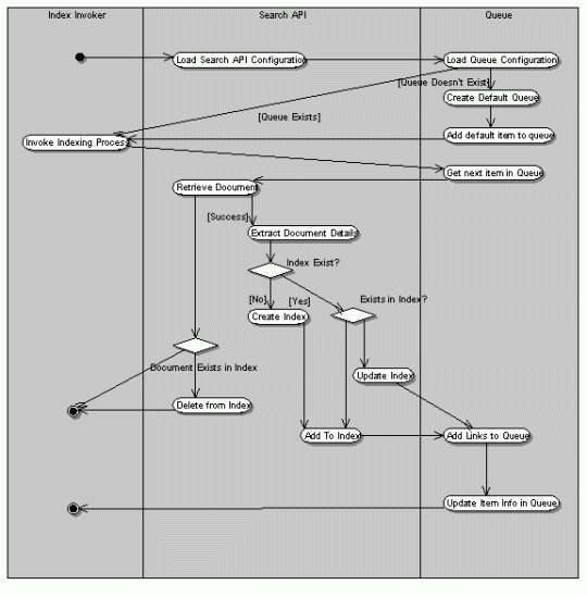
UML Activity Diagrams 18

By now, you should be able to read this diagram (and I’m tired of typing) so I’ll leave its interpretation to you.

One thing I’ve decided not to cover in this diagram is exactly what information is being indexed and how the information is being extracted from the document. This could easily warrant another activity diagram. However, I have some complex plans for these so I think I’ll leave the implementation details to another type diagram, perhaps a sequence diagram.

Do you have any comments, criticisms or questions on thisentry? If so, please leave feel free to comment below.

Search Engine API Requirements Version 2

Getting Back To UML

If you had been following my series on UML, you might be aware that I haven’t published anything on it in quite a while. Unfortunately, I got wrapped up in a few other projects which took up all of my time. Now that I’m done with my distractions, I’m going to be getting back to writing these entries on UML.

To recap where we’ve been, you might want to visit these previous entries:

Why So Many Software Projects Fail and What You Can Do About It This entry covers a few reasons why software projects tend to fail and gives some strategies for avoiding failure.

Learning UML This entry explains a bit of my motivation for learning UML. I also cover the details of a Search API I will be architecting and then building while learning about UML.

What Is UML? This entry covers what UML is and the purposes behind using UML

Acquire Your Requirements This entry covers some strategies for gathering application requirements. Good requirements help you create good UML diagrams and help avoid some of the reasons software projects tend to fail.

UML: Use Case Diagrams In this entry I make my first attempt and explaining and using UML Use Case Diagrams. Uses Case diagrams are used to analyze and illustrate the functionality of the system.

UML: Use Case Diagrams Revisited After my initial entry on Use Case diagrams I received some feedback. As a result of that feedback I decided to revise some of the diagrams created in the first Use Case Diagrams entry. (Read both!)

At the end of my last entry on UML I noted some changes which needed to be made to my requirements document. These changes have now been made. The updated requirements document can be downloaded in PDF format below.

You may also be interest to know that I’ve more or less stopped reading the UML Weekend Crash Course book. I found that it really wasn’t very informative. It had a lot of pretty pictures but no advice on how to think about UML. Since then I purchased the book UML A Beginners Guide by Jason T. Roff (ISBN: 0-07-222460-6). I like this one quite a bit more.

My next entry will probably be on Class Diagrams! As always, if you have any thoughts, feedback, criticisms, or flames, please feel free to leave a comment.

Alagad Image Component Highlighted on the Macromedia Exchange

It took a little arm twisting, but I’m proud to note that the Alagad Image Component has been highlighted on the Macromedia Exchange.

This is more for my benefit than any thing else, but here’s a screen shot for posterity:

The Image Component is Highlighted on the Macromedia Exchange

Woo Hoo!

AOL + ICQ + Yahoo + MSN + CF Event Gateways

Scott Stroz, a developer who works with Joe Rinehart and me has figured out how to get ColdFusion MX 7 to talk to Yahoo, AOL, ICQ (I think), and MSN Messenger… for free. He’s done a great job of writing it up on his blog. Read all about it here.

One Solution to this error: SQL Server does not exist or access denied

I spent almost all morning tracking down a problem where an ASP.NET app would not connect to my Microsoft SQL server. It turns out that the solution I found also applies to failing ColdFusion MX JDBC Connections.

In ASP.NET, I kept seeing this message in my logs:[DBNETLIB][ConnectionOpen (Connect()).]SQL Server does not exist or access denied. In ColdFusion, MSSQL datasources with correct connection information fail to verify.

I was pretty sure that all of my connection information was correct. My MSSQL Server was up and running, and I was logged into it using Enterprise Manager and Query Analyzer with the exact same information which were failing in .NET and ColdFusion.

I spent quite a bit of time messing around with a bunch of different settings in the SQL server and other places, but didn’t get anywhere. Out of desperation I did what I should have done first and Googled the error message. As a result I stumbled across this page. Apparently a lot of people have had this same problem for a variety of reasons.

I found the answer to the problem in the third to last comment on that page. Apparently, if you have an out of date version of the file DBNETLIB.dll Server 2003 and XP Service Pack 2 disables TCP/IP access to MS SQL Server. This is a defense against the Slammer worm.

To confirm this was the problem, I attempted to telnet to port 1433 on my localhost and could not. At this point, I was pretty sure I’d found the problem.

The solution to the problem was to go to this page on Microsoft.com and download the SQL Critical Update (SQLCritUpdPkg_ENU.exe). This update appears to deliver the needed DLL and, as a nice side effect, it patches you against the SQL Slammer worm.

After installing the patch I did a quick telnet to port 1433 and was able to connect. I then tried to use my ASP.NET app and, lo and behold, it worked just find. I also confirmed that JDBC connections to MSSQL from ColdFusion were now working and validating and I no longer had to use the (ugly) work around of ODBC.

From ColdFusion UUID to SQL UniqueIdentifier and Back Again

I had a little time today and wrote a couple of handy (and very simple) Microsoft SQL functions for converting ColdFusion UUIDs to the SQL UniqueIdentifier type and vice versa.

ColdFusion UUID to SQL UniqueIdentifier:

Pass this function any ColdFusion created UUID and it will be “converted” to be a SQL UniqueIdentifier.

CREATE FUNCTION CF2SQLUUID
(
     @guid AS varchar(35)
)
RETURNS uniqueidentifier
AS
BEGIN
    RETURN CONVERT(uniqueidentifier, LEFT(@guid, 23) + '-' + RIGHT(@guid, 12))
END

Example Usage:

<cfquery name="getUUID" datasource="myDSN">
    SELECT dbo.CF2SQLUUID('#createUUID()#') as sqlid
</cfquery>
<cfdump var="#getUUID.sqlid#" />

SQL UniqueIdentifier to ColdFusion UUID:

Pass this function any SQL created UniqueIdentifier and it will be “converted” to be a Coldfusion UUID.

CREATE FUNCTION SQL2CFUUID
(
    @guid AS uniqueidentifier
)
RETURNS varchar(35)
AS
BEGIN
    RETURN LEFT(CONVERT(varchar(36), @guid), 23) + RIGHT(CONVERT(varchar(36), @guid), 12)
END

Example Usage:

<cfquery name="getUUID" datasource="myDSN">
    SELECT dbo.SQL2CFUUID(newID()) as cfid
</cfquery>
<cfdump var="#getUUID.cfid#" />

Add your own functionality to the Alagad Image Component

Although the Image Component has all of the most requested functionality, from time to time I get requests for features I can’t or won’t implement. Lucky for these users, they can easy to add features to the Image Component themselves! I tend to get two types of feature questions or requests. These can be categorized as follows:

  • Does the Image Component write to GIF Files?
  • Does the Image Component support a particular type of functionality in a particular way?

Let me address these below.

Does the Image Component write to GIF Files

The short answer to this question is no. (But keep reading!) The Image Component leverages classes provided by the Java platform underlying ColdFusion. The classes which come with Java do not support writing to GIF files so the Image Component does not natively support writing to GIF files.

But wait! You can still write to GIF files, it’s just a little harder.

The Image Component uses a Java BufferedImage internally to store image data. However, you as a user of the Image Component, have access to this data via the getBufferedImage() and setBufferedImage() methods. This means that you can grab the raw data the Image Component is working with, manipulate it and, optionally, put it back into the Image Component. This also means that anything you can do to a BufferedImage you can do with help from the Image Component.

How does this relate to writing GIF images? Well, today I stumbled across this page: http://www.acme.com/java/software/Acme.JPM.Encoders.ImageEncoder.html. This page shows the Java Docs for a freeware Java GifEncoder class. This particular class is part of a larger package provided by ACME Laboratories (no association with Wile E. Coyote). Read the website for more information about ACME.

You may note that the GifEncoder method accepts an Image object and an OutputStream object. Coincidently, Image is the superclass for BufferedImage! An OutputStream is also quite easy to create from ColdFusion. I’ll show you how in a second.

If you download the ACME package and extract it into a Java class path you will have the beginnings of the ability to write GIF images from the Alagad Image Component. I am running ColdFusion on top of JRun, so I extracted the ACME package into my c:JRun4lib directory. You will need to figure out where to extract this package yourself. Don’t forget to restart ColdFusion before continuing.

Once ColdFusion was done restarting, I created a new CFM page and started coding. I started by reading an image:

<!--- create the Image.cfc and read an image --->
<cfset myImage = CreateObject("Component", "Image") />
<cfset myImage.readImage(expandPath("transparentImage.png")) />

The GifEncoder class’s constructor requires an Image object and a Outputstream. So, I added the next few lines of code.

<!--- get the bufferedImage from the Image Component --->
<cfset BufferedImage = myImage.getBufferedImage() />
<!--- create a FileOutputStream (a type of OutputStream) and init to the image to write to --->
<cfset FileOutputStream = CreateObject("Java", "java.io.FileOutputStream").init(JavaCast("string", expandPath("myOtherImage.gif"))) />

Once this code was in place I had everything I needed to write a Gif except a GifEncoder! This next line helped out with that:

<cfset GifEncoder = CreateObject("Java", "Acme.JPM.Encoders.GifEncoder").init(BufferedImage, FileOutputStream) />

Now I had a GifEncoder which was configured to write my PNG image to a GIF file, “myOtherImage.gif”. Just one more line of code to actually do the job:

<cfset GifEncoder.encode() />

The very first time I ran this code it worked like a charm! My transparent PNG was successfully converted to a transparent GIF. Woo Hoo!

So, that’s a good example of how to use getBufferedImage() and a little creative Java-from-ColdFusion to do things which the Image Component can’t itself do.

But, it gets even better! Check out the next example, and be sure to see the last section too!

Does the Image Component support a particular type of functionality in a particular way?

Once again, the short answer to this question is no. But, you guessed it; there is a way to add most any functionality to the Image Component. Here’s a good question I received the other day:

I’m watermarking images with a logo. However, I don’t want to be required to calculate the location for the watermark image each time I do this. Is there any way to simply say “Draw an image in the lower right corner, or the center top of the Image?”

Well, the Image Component does provide a way to watermark images by drawing one image into another with the drawImage() method. However, you’re responsible for the calculations involved in determining where the new Image should be placed.

If you wanted to place an image in the bottom center of another image you could perform the following steps:

  • Read the watermark image and get its width and height
  • Read the image being watermarked and get its width and height
  • Subtract the height of the watermark from the height of the image being watermarked to get the Y coordinate for drawing.
  • Subtract the width of the watermark from the width of the image being watermarked and divide that number by two to get the X coordinate.
  • Draw the watermark into the image using the drawImage() method, passing it the coordinate information.

This could easily be modified to place the watermark in various locations, but I’ll leave that to you. Here’s the code implementing the steps outlined above:

<!--- create the two image objects --->
<cfset myImage = CreateObject("Component", "Image") />
<cfset myWatermark = CreateObject("Component", "Image") />
<!--- read the image and watermark --->
<cfset myImage.readImage(expandPath("forest1.jpg")) />
<cfset myWatermark.readImage(expandPath("watermark.png")) />
<!--- get the image's width and height --->
<cfset imgWidth = myImage.getWidth() />
<cfset imgHeight = myImage.getHeight() />
<!--- get the watermark's width and height --->
<cfset waterWidth = myWatermark.getWidth() />
<cfset waterHeight = myWatermark.getHeight() />
<!--- get the coordinates to draw into --->
<cfset x = Round((imgWidth - waterWidth)/2) />
<cfset y = imgHeight - waterHeight />
<!--- draw the watermark into the image --->
<cfset myImage.drawImage(expandPath("watermark.png"), x, y) />
<!--- write the new image to disk --->
<cfset myImage.writeImage(expandPath("watermarkedImage.jpg"), "jpg") />

And here’s the resulting image when I run the code:

The Big Picture

Now wouldn’t it be cool if you could add methods to the Image Component to do these two things? Once again, you guessed it; you can! This time it’s simply a matter of extending the Image.cfc file. The following example creates a new CFC named “superImage.cfc” which extends Image.cfc and adds the ability to draw images into the bottom center of your image and allows you to save the images as a GIF file. This is all in addition to everything else the Image Component can already do!

The following code encapsulates all of the functionality discussed above into two methods in a component which extends the Image Component:

<cfcomponent displayname="SuperImage" extends="Image" hint="I add a few methods to the Alagad Image Component.">
    <cffunction access="public" hint="I write a gif Image!" name="writeGif" output="false" returntype="void">
        <cfargument hint="I am the path to write the GIF image to." name="path" required="yes" type="string"/>
        <cfset BufferedImage=getBufferedImage() var/>
        <cfset FileOutputStream=CreateObject("Java", "java.io.FileOutputStream").init(JavaCast("string", arguments.path)) var/>
        <cfset GifEncoder=CreateObject("Java", "Acme.JPM.Encoders.GifEncoder").init(BufferedImage, FileOutputStream) var/>
        <!--- write the gif image! --->
        <cfset GifEncoder.encode()/>
    </cffunction>
    <cffunction access="public" hint="I draw an image into the center bottom of the current Image." name="drawImageInCenterBottom" output="false" returntype="void">
        <cfargument hint="I am the path of the image to draw." name="path" required="yes" type="string"/>
        <cfset myWatermark=CreateObject("Component", "SuperImage") var/>
        <!--- get the image's width and height --->
        <cfset imgWidth=getWidth() var/>
        <cfset imgHeight=getHeight() var/>
        <!--- declare the watermark's width and height --->
        <cfset var waterWidth=0/>
        <cfset var waterHeight=0/>
        <!--- declare x and y --->
        <cfset x=0/>
        <cfset y=0/>
        <!--- read the watermark --->
        <cfset myWatermark.readImage(arguments.path)/>
        <!--- get the watermark's width and height --->
        <cfset waterWidth=myWatermark.getWidth()/>
        <cfset waterHeight=myWatermark.getHeight()/>
        <!--- get the coordinates to draw into --->
        <cfset x=Round((imgWidth - waterWidth)/2)/>
        <cfset - waterHeight y=imgHeight/>
        <!--- draw the watermark into the image --->
        <cfset drawImage(arguments.path, x, y)/>
    </cffunction>
</cfcomponent>

The following is some code using our new SuperImage component:

<cfset mySuperImage = CreateObject("Component", "SuperImage") />
<cfset mySuperImage.readImage(expandPath("someCrazyImage.png")) />
<cfset mySuperImage.drawImageInCenterBottom(expandPath("watermark.png")) />
<cfset mySuperImage.writeGif(expandPath("myGif.gif")) />

Now how cool is that?! Can you do that with any competing image products? I think not!. No go buy yourself a dozen licenses for Image Component, already!

Tag Cloud